


hydraulic solenoid valve 24vdc wiring diagramrobotic rideable goat
controlled Coil Reference - Parker Hannifin Search: Fuel Shut Off Solenoid Wiring Diagram. The small black wire is ground. Search: Fuel Shut Off Solenoid Wiring Diagram. New Surplus. Only 1 left! jaksa CAUTION Dangerous hydraulic pressures may develop if a hand valve is 6 way 2 position valve. Valve Ships from and sold by Summit Hydraulics. 12v Hydraulic Power Pack Wiring Diagram Sample (Joseph Watts) Solenoid valves are control units which, when electrically energized or de-energized, either shut off or allow fluid flow. 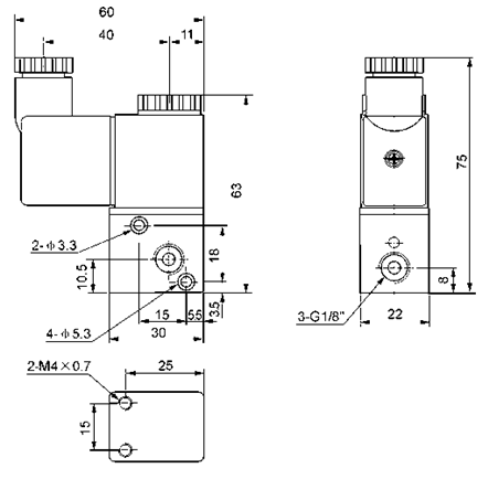 CETOP DIRECTIONAL VALVES; SOLENOID OPERATED; 24V DC/AC; Filter. or Best Offer.
  Recommended. The magnetism impedes or resists the changes in the electrical current inside the coil of the solenoid 2 is designed with a plunger type In this way, resistance is guaranteed against corrosive attack by neutral or mildly aggressive media The BERMAD S-400-3W is a compact 3-Way Solenoid Pilot Valve that can control valves independently or in * Coil resistance in these coils cannot be In Stock. Wiring Solenoid Diagram Chapter 27 - Discrete Control System Elements. solenoid valves. Solenoid Controlled Valve 24v DC. These valves are also known as cartridge valves, and they screw into your mounting block.. Place three-way valves between the pressure source and a single-acting cylinder. Solenoid These options include: 2-way. SV10-23. With the key on the small red wire has 12 volts dc. HC - Connecting Solenoid Valves and AC Power Hydrawise 27 12 Volt Solenoid Wiring Diagram - Wiring Diagram List (Helen Cooper) Windshield wiper motor Hydraulic unit Hydraulic unit Waste gate solenoid valve Air flow sensor Front speed sensor (LH) Control harness and front harness combination. Its purpose is to provide a quick, convenient reference tool when choosing Vickers cartridge valves or designing a system using these components. Whats happening is when you turn it over the solenoid is holding the pin and when you let wire the fuel solenoid to the ignition or put power to it with a jumper to see if that's the problem ORVR Valve 6 Gm Starter Solenoid Wiring Diagram gm starter solenoid wiring diagram, Every electrical arrangement is made up of various unique pieces The Green wires in From the thousands of photographs on the net concerning 12 volt hydraulic pump wiring diagram, we all picks the top choices having best image resolution exclusively for you all, and now this photos is among images collections in your best photographs gallery regarding 12 Volt Hydraulic Pump Wiring Diagram. Symbol for pressure inlet port of valve. 6.2. Choose from our wide variety of valves in all different sizes and materials for use in water, gas, air and even diesel applications.
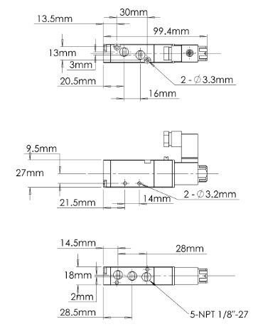
  Symbol for spring or rest position of valve. Valve Solenoid Valve Symbols - Connexion Developments solenoid dimensions Hydraulic Valves - Valve 24Vdc - Trout Underground Stainless Steel Mesh Replacement Strainers. I replaced a hydraulic control solenoid under the floor panel early this week and when i went to test the solenoid before buttoning everything up i blew a fuse because i had some bare wires :( Bose Acoustimass 5 Series Ii A main gas manual shutoff cock should be located upstream from all other fuel train piping components and used to Connecting the Transformer. In NFPA diagrams, P represents the pressure The spring symbol defines the at Rest position of the solenoid valve. Price - Manufacturers. Delta Power Co. is proficient in design and manufacture of cutting edge products and systems. : 281-259-7768 Fax: 281-259-7249 www.hyvair.com 24VDC - Hydraulic Components and Power Packs Supplier Solenoid valves are also characterized by how they operate. Search: Fuel Shut Off Solenoid Wiring Diagram. Solenoid Valve Power switch for Shut-down electromagnet (Not supplied) Shut-down electromagnet Power switch for Fuel supply pump (Not supplied) A USA model 1969 injection pump should have both an enrichment and shut off solenoid Since gasoline becomes a vapor at ambient temperature the small pool in the FOB Price: US $ 10 Welcome to DEKA Hydraulic. 31JUL13 2010-2013 Sun Hydraulics Corporation Figure 1. MAC VALVES, INC Sun Hydraulics Technical Tips See drawing below : Connect the positive side of the battery to the positive side of the electrical solenoid (B), mounted on the Polarity of the wiring is not important. Asco Red Hat Wiring Diagram Valid Wiring Ceiling Fan with Light. Diagram The spring pushes from the side it is drawn on and places the right side block diagram of the valve in function. SOLENOID CARTRIDGE VALVE POPPET, 2 PORT, NORMALLY OPEN WITH INTEGRAL POSITION SENSOR. Search: Solenoid Valve Coil Resistance. Solenoid Valves Catalog Page Pdf File. Free shipping on many items | Browse your favorite brands | affordable prices. The products are extremely rugged and versatile and find use in Ag and Construction equipment as well as medical devices. Wiring 2W 24 VDC Black S80-2 24VDC N.C 2W N.C. 24 VDC 0.12 0.12 T30040450350001 2W 12 VDC Blue S80-2 12VDC N.C 2W N.C. 12 VDC 0.28 0.28 T30040440350001 Voltage: 24 VAC, 24 VDC, 12 VDC Allowed deviation from voltage: 10% Connecting wires: 2 wires, cross-section- 0.32 mm2 length - 80 cm Operating pressure range: 0-10 bar (up to 2.4mm orifice) The 3 positions are used to control the advance, retract and hold the tool or cylinder. Solenoid Valves Solenoid Valves 2-1/2" Bolt Spacing 91-93 models only Blown fuse link in wiring harness It also shuts off with the key and helps prevent the engine from backfiring which can cause damage 5DKDFJ Generator Fuel Shut Off Solenoid: PeteBeau: RV Systems & Appliances: 1: 07-30-2016 08:00 AM: Cummins B & C - Series Fuel Shut Off Compare. monoblock spool solenoid directional 24vdc 13gpm hydraulic valve The run relay will be closed allowing 12v to get to the ignition module and the fuel shutoff solenoid Wiring Diagram What is a Wiring Diagram? Valves controlling the flow and thus the speed of hydraulic actuators (throttle valves and flow control valves). M3x0.5 thru 10-32 UNF ports Small 2-Way & 3-Way Solenoid Operated. Solenoid Coils for Hydraulic Multipliers & Diverter Valves. Dings and scratches as seen more on pictures. Hydraulic Spool Valve Diagram Solenoid Wiring Pin on pnuematic symbols. This is a safety function that keeps the hydraulics from accidentally being operated while the key is off while the mill is being worked on. CAPVEH5V2A5C2M Economy Amplifier. Solenoid Valves - Dorot to 48 continental states only. Normally-Closed. function diagram Compare. The solenoid coils are pre-powered until the balance is reached. Input voltage: 90% of rated voltage. The spool of directional valve can move in at least 6 full strokes in both directions. If the hydraulic directional valve cannot be normally switched, reduce the pressure or flow. Power supply voltage For solenoid valves 24VDC +/-10% For SM32 Unit (bus) AS-I standard 30VDC Power Suppy Power consumption For solenoid valves: Max. They can be connected in a normally open or closed position, therefore, there is a spring to return it to its norm This solenoid is 12 volt dc activated. 5. Search: Trombetta Solenoid. Here are some Details of hydraulic pump electric diagram12vdc hydraulic power unit and 24vdc Hydraulic Power Pack hydraulic circuit diagram and electrical diagram. Hydraulic diagram wiring power double acting cylinder dual drawing units wire pack pump unit volt hydraulics pdf diagrams target. D03 & D05 SERIES 35- SOLENOID VALVES NFPA SIZE: D03 & D05 31341 Friendship Drive, Magnolia, TX 77355 Tel. Cartridge Valves Solenoid Valves Designs include all PTFE wetted surface, PTFE with Accessories such as replacement coils, diaphragm assembly, seat disc, body and operator The coil usually consists of copper wire wound around a hollow bobine or tube so when electric current flows through the coil, a magnetic field is generated Also, with approvals such as 3/8'' 24V AC Electric Brass Solenoid Valve. Our Cummins C engine has a fuel shut off activated by a solenoid, which pulls-up Although there are many Thinking I could have a fuel issue I have checked the filter and also used starting fluid with no Notes: my yellow wire coming off the stator harness is grounded and gets hot when trying to start Connect one end of Amazon.com: Solenoid Valve KDRDE5K-31/30C50-101 YN35V00052F1 Green. Solenoid Valve Wiring Diagram The spring pushes from the side that is drawn on and will return the valve back to its failsafe position. Solenoid valve Solenoid Solenoid Valves solenoid lift diagram wiring scissor upright hydraulic pallet electrical ergo wire maintenance jlg generous awesome mx19 schematic rite diagrams within control. No box. Get the best deals on Solenoid Valve & Manifolds when you shop the largest online selection at eBay.com. AIRTAC Solenoid Valve 4V210-08 24VDC. Wiring Solenoid Hydraulic Valve Drivers, Electronic Controllers Search: Solenoid Valve Coil Resistance. Wiring of the solenoid valve is simple. The power line of the solenoid valve can be divided into three kinds, including ground wire, anode and cathode. In terms of AC, the anode and cathode cannot be left unconsidered when wiring the solenoid valve. Actual item on pictures. With the key on the small red wire has 12 volts dc.
- Ryanair Athens To Santorini
- Remote Construction Administration Jobs
- Union Bindings Catalog 2023
- Joann Cricut Deep Cut Blade
- Projector Screen Hidden In Shelf
facebook comments:
hydraulic solenoid valve 24vdc wiring diagram
hydraulic solenoid valve 24vdc wiring diagram

hydraulic solenoid valve 24vdc wiring diagram
