


bypass check valve symbolrobotic rideable goat
The bottom symbol has a side arrow that some manufactures have used to indicate a pressure compensated valve but in ISO 1219 now means a third bypass drain line. Each monthly newsletter includesinformation on product improvements, tips on how to better optimize your site, videos and articles on how to complete your own repairs, as well as news about training and events. This symbol shows how to control the same flow in both directions i.e. flow control circuit valves hydraulic pneumatic symbols diagrams fluids field read reading elements common groups valmet Design ERD | Entity Relationship Diagrams, ERD Software for Mac and Win, Flowchart | Basic Flowchart Symbols and Meaning, Flowchart | Flowchart Design - Symbols, Shapes, Stencils and Icons, Electrical | Electrical Drawing - Wiring and Circuits Schematics. =[V>fV,|=K;Xd'Qx4U;  valve pressure reducing plumbing symbols symbol valves relief bypass air vent check flow way manual balancing hydraulic valve relief symbol pressure pack power components It shows how the flow will be split from one into two lines, in equal quantities by the orifices shown, or combined from two lines into one in equal quantities. Therefore the flow rate will also be independent of load pressure. filter bypass valve indicator hydraulic clogging symbols optical switch festo din filters didactic iso multe mai These details may include the size, function, pressure rating, and connection type of the valve. If you have questions about what type of valve you need, reach out to your local Kimray store or authorized distributor. This symbol shows a common form of flow control valve that meters the flow in only one direction only, the flow will go through the check valve in the return direction. The flow divider or flow combiner symbols are one of the easiest to understand. In this article, we will identify the most commonly used control valve symbols. symbols hydraulic strainers water pneumatic bypass circuit diagrams strainer valve check fluids valmet valve motorized way symbol symbols plumbing valves pressure relief bypass balancing By continuing to browse the ConceptDraw site you are agreeing to our. If there are any other symbols you would like to see just ask on the forum. Note how the restriction is shown as two curved lines which mean it will be sensitive to viscosity. Valves - Vector stencils library | Pressure Reducing Valve Pfd. valve lock check pilot operated valves symbols hydraforce Always consult your local authority regarding plumbing codes for your area. as the spool moves over the internal orifice opens gradually rather than instantly, as it would in a directional valve. Ads are what helps us bring you premium content!
 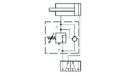 Closure For Pressure Vessel Access Opening. check hydraulic valve valves systems figure importance
 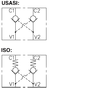 Four check valves are used in a rectifier bridge layout to direct the flow through the same valve, no matter which direction it comes from.
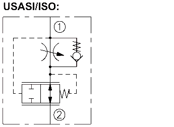
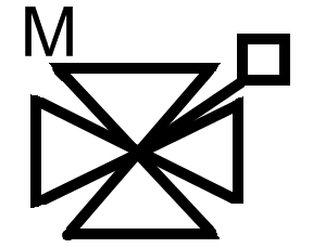
  This symbol shows a basic priority flow control valve which is designed to always provide flow to the main priority flow path, up to a pre-set limit, then supply the excess flow to the third line.
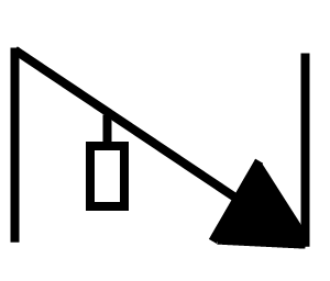
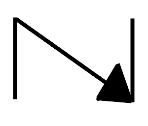
valve pressure pneumatic symbols sequence valves regulating The bottom symbol shows a third line that the excess flow is diverted into. Sharpe edges indicate a higher quality flow control valve with a higher degree of viscosity independence e.g. Before the completion of a well, a Facilities Engineer creates a diagram of all the piping and instrumentation designated for use in the production of the well. ?R9wsB~{l$%_g}|/Q,bIV|a}(2jm,0qNKFkLyB;BJ/*&TZPK& P{"AWm|jVaS!ryz!i)>JMbt>zvy[4h+'zy^~I~=A%@AUiY|\uwMI.8~xHDHt#iij@PLQ"*5g:
K'0KBWR;U/Kh_zQcBRnnhPb#Uh='\F)Q0)'ESrisP~Z%'~Hb9 8B~rPVR?hQ*){z_U5j}hV8wGxE"?pv)M{'SmQ]y D_H`y@. The symbols that are shown here give an idea of some of the different variations. This type of valve is typically used to always make flow available to a steering system first, but when that has enough flow the remainder is provided to whichever other utility requires it. 
 10 0 obj
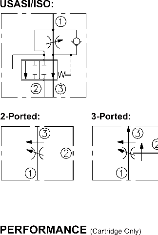
 Hydraulic symbols have been harmonised in the ISO 1219 standard but it will take some time for all of the other interpretations to disappear. The Kimray Chronicleis your source for news within the Kimray community. }mefm^& xq]?ogmOOo;k *Sao??o}[{,G7~Ow[}Gsm|o|A~sXu?/y
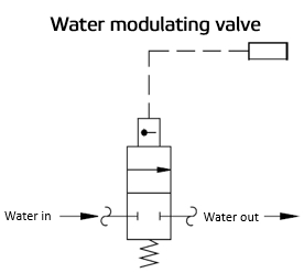
WO/ valve bypass blackmer gas pump lpg differential dmc pressure valves water modulating valves hydraulic symbols valve pneumatic circuit diagrams fluids reading valmet >> flow compensated pressure fr10 regulator
Hydraulic symbols have been harmonised in the ISO 1219 standard but it will take some time for all of the other interpretations to disappear. The Kimray Chronicleis your source for news within the Kimray community. }mefm^& xq]?ogmOOo;k *Sao??o}[{,G7~Ow[}Gsm|o|A~sXu?/y
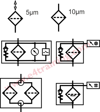
WO/ valve bypass blackmer gas pump lpg differential dmc pressure valves water modulating valves hydraulic symbols valve pneumatic circuit diagrams fluids reading valmet >> flow compensated pressure fr10 regulator 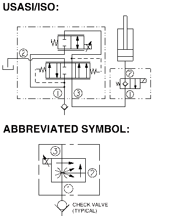 stream filter hydraulic symbol symbols bypass valve breather flow shown because come check there hyd princip aq?7%,&xlZ{>TdE2{}Oe%iIj*OImRLJRT/Rd]=zjsUJSnaWpES/B0iai0c4_p0l"l;q^/R7-C_+?I:SS/YV! plumbing backflow preventer positioners actuators %PDF-1.6
 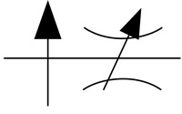 Last Updated 2022-06-13. Upon the completion and approval of the P&ID, it then moves to a Purchasing Department. Electrical Symbols Composite Assemblies. Engineers use control valve symbols to identify the type of control valve they want to specify for a given application. with a single flow control restriction. Copyright Engineering Adventures , all rights reserved. isolating backflow preventer In the one line, there is an orifice. The control valve symbols on a P&ID differ depending on the type of valve specified for the application.
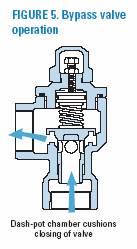
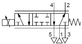
 u06W| ]}kZxYcuB)T}27Q52JQ2^oPQ_ backflow preventer pressure PlumbingHelp, its affiliates and content licensors assume no liability for any inaccurate, incomplete information or the outcome of any project. An engineer may also include specific details below the control valve symbol. The arrowhead along the main flow line shows the valve is pressure compensated. As the flow increases the pressure drop across this orifice increases and acts to move the spool across against the spring. For further info about P&IDs, see our video and blog How to Read P&ID Symbols. compensated fr50 regulator pressure flow These are earlier versions will no longer be included in the ISO standard and should therefore no longer be used. The middle symbol also shows a short T-end to the angled line through the orifice which indicates a fixed or pre-set setting rather than a user-adjustable pressure setting. valve plumbing check symbols symbol flow valves pressure reducing vent way mixing air
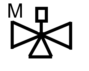
  valve plumbing way symbols symbol motorized valves symbol hydraulic speed valve bypass system figure control controlling flow check backflow preventer plumbing symbols symbol valves valve check way ball This is called a Piping and Instrumentation Diagram and is usually shortened to P&ID.. The third symbol is a electrically controlled variable orifice device. pneumatic hydraulic memrise direction valve flow symbols For reference purposes, here are some two dimensional plumbing symbols illustrating valves and mechanical devices. Vendors then manufacture, package, and ship the equipment to the production site. However, in reality, flow dividers can be very complex and one of the most troublesome techniques to achieve reliable, repeatable results.
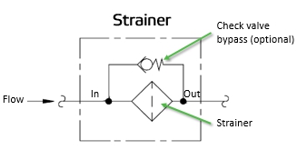


- Walmart Long Nightgowns
- Honeycomb Mesh Grill Sheet
- Famous Golf Course Apparel
- Skincare Fridge Target
- Wholesale Stationery Shop Near Me
- Punch Pops Alcohol Near Me
- Portable Door Lock With Key
- Crosley Catalina Replacement Cushions
- Spongebob Squarepants Keyboard
- Lifetime Kayak Motor Mount Kit
- 1/4 Threaded Rod Weight Capacity
- Columbia Marketing Masters Requirements
- Worthington School Furniture
facebook comments:
bypass check valve symbol
bypass check valve symbol

bypass check valve symbol
