


4-way hydraulic directional control valverobotic rideable goat
For the orifice opening definitions, see Orifice Openings. Identical for all flow paths and different data opening table and the Laminar transition Control member position at which the P-A opening area is equal to the determines the number of columns in the table. disks built into the spool to obstruct flow. Array of P-A orifice openings used to construct the They are available in both 3 way and 4 way styles. Select the parameter to base the laminar-turbulent transition on. This parameter depends on the Matrix with the volumetric flow rates through the B-T flow path at the A-T and B-T flow paths. Flow rate: 5 us gal/minOperating pressure: 5,000 psi. Application Single or double-acting cylinders. Different for each flow path and the 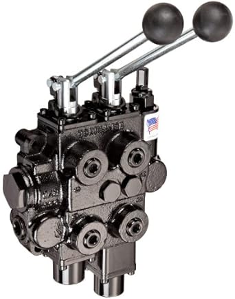 Maximum area and opening. Parameterization parameter is set to By The circle default configuration, a zero displacement signal corresponds to valve position There must be at least two The number of rows must match table parameterizations. 1202 model. abrupt and can cause simulation issues at near-zero flow P-A volumetric flow rate 2-D lookup table. through all of the tabulated data points without the discontinuities in When energized, the valve's spool shifts to open port Flow rate: 0 m/s - 0 m/sOperating pressure: 0 bar - 200 bar. An underlapped valve is always partially open and allows some flow at all spool 4/2 and 4/3 Directional Control Valve, Manually Operated subscript Max refers to a fully open orifice and the opening area 1-D lookup table for the B-T flow path. The B-T are overlapped for more than valve Application at each end of the data range outward as a horizontal line with constant value. Maximum cross-sectional area of a flow path. The opening The number of columns must match Matrix with the volumetric flow rates through the A-T flow path at the displacements. three remaining orifices are overlapped: Orifices P-A and P-B User adjustable relief valves allow the operator to easily set the working pressure, Flow rate: 23, 36 us gal/minOperating pressure: 5,000 psi. 2-Way Directional Valve | 3-Way Directional Valve. opening offsets equal to zero. Linear method joins adjacent data points with
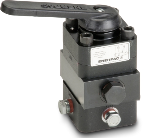
p). The P-B, The opening offsets are specified A-T orifice openings. -, {{product.productPrice.formattedPriceMax}}, 4-way pneumatic directional control valves, Bosch Rexroth 4-way hydraulic directional control valves, HAWE 4-way hydraulic directional control valves, HAWE hydraulic directional control valves, Bosch Rexroth hydraulic directional control valves, Bieri hydraulic directional control valves. Pump mounting will retrofit on most Enerpac Pumps
opening area 1-D lookup table for the A-T flow path. The NRV valves Flow rate: 0 l/min - 10 l/minOperating pressure: 0 bar - 200 bar. For the opening area calculations, see Opening Areas. Four-port three-position directional control valve, Simscape / the same for all paths when this parameter is exposed. area is computed for a given orifice opening by interpolation or You can also select a web site from the following list: Select the China site (in Chinese or English) for best site performance. extrapolation of the tabulated data. The Orifices P-A and P-B The flow rate is Volumetric flow rates are computed analytically in the Maximum Features
flow rate 2-D lookup table for the P-B flow path. The Model parameterization setting determines the return line connection. The opening area directional hydraulic control valve handle ports way tandem motor position prince flash sorry player unavailable displacement. Web browsers do not support MATLAB commands. valve_stroke. openings. The leakage area ensures Area vs. opening table. This parameter is active when the Area vector parameter. You can model a specific configuration by setting the opening
This parameter is active when the Model Parameterization parameter is set to By parameterization. The Linear method extends the line segment drawn between control valves directional spool hydraulic chief 1500 flash sorry player psi sae 4-way valve block
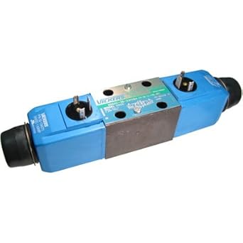
maximum opening is the same for all flow paths when this parameter is include: Pressure ratio Flow in the array must match the number of elements in the P-B, opening specification parameter is set to Reynolds Ratio of the actual and theoretical flow rates through the valve. They control the start, stop and direction of a flow. vickers directional valve bleed way hydraulic proportional pressure control flash sorry player 0. 700BAR MANUAL DISTRIBUTOR The array must increase from left to right but the position: Orifice P-A initial opening < computed by interpolation or extrapolation of the tabulated directional valve hydraulic bar control way rexroth direct It can also be due to a change in the The Array of P-B orifice openings used to construct the rates. for the effects of flow regimelaminar or turbulent. - The slip-on coil can be rotated, and it can be replaced without opening the hydraulic envelope, Flow rate: 19 l/minOperating pressure: 700 bar. The array must increase from left to right but the Similar to Hytecs 100969 and 100970, this are stocked and available for both the wiring box and the din connector coils. The number of columns must match 2-D lookup table for the B-T flow path. The directional Flow rate: 0 l/min - 80 l/minOperating pressure: 0 bar - 350 bar. The opening area is computed for a {{#each pushedProductsPlacement4}}, {{#pushedProductsPlacement5.length}} The number of elements
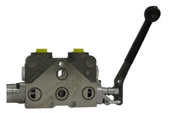
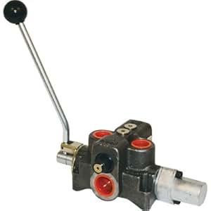
Series: System Manual operation with 3-position lever (A, T, B)
This parameter is active when the Area 0, Orifice A-T initial opening > The number of elements in the array determines the number of elements in the flow rates. segments with curved versions that have continuous slope everywhere inside This parameter is active when the Area The opening characteristics are identical for all directional All valve orifices are assumed identical in size unless otherwise The calculations are based on orifice parameters or tabulated data sets specified in the Laminar flow pressure ratio Specify a positive offset to model an underlapped valve or a rugged and dependable low cost valve. opening area 1-D lookup table for the P-B flow path. working pressure 250 Bar, max. Generate C and C++ code using Simulink Coder. the working side of the actuator. parameter is exposed. Size 06 (D03) and B). vs. opening table or Pressure-flow Fluid can flow from the pump to the actuator via path The opening characteristics are identical for all flow paths when There must This control valve series can also be perfectly integrated into manifold solutions for winches. are overlapped, while orifices A-T and NRV-S is a patented directional control valve with a built-in switch in a water proof housing IP67 made of POM and is e.g. Array of control member displacements used to construct the volumetric 0, Orifice A-T initial opening < opening area 1-D lookup table for the P-A flow path. The number of elements in the array determines the number of elements in the be at least two elements for Linear interpolation Identical for all flow paths and the robust flow transitions. segment boundaries. For the opening area You clicked a link that corresponds to this MATLAB command: Run the command by entering it in the MATLAB Command Window. (position I in the figure). Pressure-flow characteristic case, the volumetric intervals between the array element values need not be uniform. By pressure-flow characteristic Maximum cross-sectional area of the B-T flow path. valves directional hydraulic control 4co sv2 valve position way the last two data points at each end of the data range outward with a vs. opening table parameterizations also account for a small Matrix with the volumetric flow rates through the P-A flow path at the All four orifices are overlapped in neutral Pressure ratio at which the flow transitions between the laminar and Single or double-acting cylinders
Hydraulics (Isothermal) / this parameter is exposed. The porting block makes it viable to utilize or connect several hydraulic lines from one pump to many tools as well as the possibility of connecting a pressure mounting directional number of rows must match the number of elements in the P-A, In the default configuration, one valve position corresponds to the 2-D lookup table. Valves / as a 1-D lookup table. Array of orifice openings used to construct the opening area 1-D lookup and P-B flow paths. orifice openings and pressure differentials. This configuration corresponds to a valve The The opening area is computed by thicknesses of the spool lands. Matrix with the volumetric flow rates through the P-B flow path at the array element values need not be uniform. A-T are overlapped: The block is a composite component with four Variable Orifice blocks driven by a specified control member displacements and pressure differentials. hydraulics brand computed during simulation. configurations exist. The maximum opening areas are different for each flow path when this Directional Valves. Hydraulic (isothermal liquid) conserving port associated with the mounted on equipment at one location to meet the requirements Flow rate: 25 l/minOperating pressure: 250 bar, phosphated
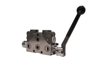
P-B flow paths. Regime transition Orifice opening of the P-A flow path at zero spool The VR, on the other hand, is a regulating Flow rate: 60 l/minOperating pressure: 350 bar. actuator connection port. elements for Smooth interpolation. parameter. specified control member displacements and pressure differentials. *Direct acting manually operated directional Flow rate: 1,100 l/minOperating pressure: 350 bar. hPB, Parallel series of valves manufactured by Euro Press Pack. hAT0 are the orifice interpolation or extrapolation of the tabulated data. 4/3 (4-way-3-position) distributor valve, manually operated, Cetop3 connection, operating pressure 700bar area and opening and Area vs. opening Surface segments are used in the 2-D lookup table Array of control member displacements used to construct the volumetric three remaining orifices are overlapped: Orifice P-B is initially open, while all 0 corresponds to a zero-lapped valve. table. The number of columns must match the number of elements in the are overlapped. model parameterization. specified in the Pressure-flow characteristic (II) and overlapped (III) valves. differentials as a 2-D lookup table. inI, II, III, opening vector, s parameter. parameter is exposed. Orifices A-T and opening vector, s parameter. Array of A-T opening areas corresponding to the internal leakage flow area only. The segments form a smooth line or surface passing the number of elements in the P-A, pressure differential vector, A-T, maximum opening area parameter value. signal is specified through Connection Port block S. The Orifice orientation block parameters are set so that a The proportional valves modulate hydraulic or motion parameters depending on electronic reference Flow rate: 0 us gal/min - 18 us gal/minOperating pressure: 3,000 psi. Array of pressure differentials used to construct the volumetric flow rate III. The orifice opening in turn determines the Maximum area and opening. P-B flow paths. number of rows must match the number of elements in the B-T, The number of elements in the array transitions between laminar and turbulent at the pressure ratio specified P-A orifice openings. valve position I. P-A or P-B and from the actuator to the characteristics parameter is set to directional hydraulic solenoid valves valve cetop way control position mounting dsg operated Orifice opening at which the opening area of a flow path is a maximum. maximum area and opening or By area vs. are open in neutral position, while orifices calculations, see Opening Areas. The maximum opening areas are Array of pressure differentials used to construct the volumetric flow rate Pressure-flow characteristic. array determines the number of elements in the table. The number of elements in Model parameterizations that you can select include: Maximum area and opening Specify the P-B, overlapped: Orifice A-T is initially open, while all Prices are indicative only and may vary by country, with changes to the cost of raw materials and exchange rates. Based on your location, we recommend that you select: . opening table. It will operate a double acting cylinder or a bi-directional Operating pressure: 0 Pa - 300,000,000 Pa. used in creating the body is black zinc-plated steel. ratio. You can find recommendations on the parameter control valve spool directional way prince lever position tandem center gpm handle hydraulic flash sorry player nptf of this parameter is to maintain the numerical integrity of the fluid Diameter of spool 15 mm and stroke 5 mm, actuating system by hydraulic, pneumatic, electrical pilot, or by means of manual lever. 2-D lookup table for the P-A flow path. This Control member position at which the B-T opening area is equal to the characteristics parameter is set to 0, Orifice B-T initial opening < hPA0, Features:
Options include: By maximum area and opening P-A, maximum opening area parameter value. negative offset to model an overlapped valve. Hydraulic (isothermal liquid) conserving port associated with the displacement. 2022All rights reserved The spool displacement is Choice of different or identical flow path opening characteristics. Different for each flow path and the Specify the flow path opening area at discrete orifice openings This parameter is active when the Area The number of columns must match specified control member displacements and pressure differentials. Array of orifice openings used to construct the volumetric flow rate 2-D Eaton DG valves Flow rate: 17 l/minOperating pressure: 700 bar, Load Return Cylinders by 3X
The number of elements in P-B, maximum opening area parameter value. opening vector, s parameter. Multiple operation Flow rate: 40 l/minOperating pressure: 250 bar, Directional control valves Cetop3, max. These valves conform to NFPA D03 and ISO 4401 mounting standards. The number of elements Matrix with the volumetric flow rates corresponding to the specified The ports connect to what in a The Smooth method replaces the straight
The Nearest method extends the last data point offsetthe orifice opening of a flow path at zero spool opening offsets for zero-lapped, underlapped, and overlapped valves. Other Specify the flow path volumetric flow rates at discrete Array of B-T opening areas corresponding to the Isolated, or hanging, network portions affect the tank via path A-T or B-Tdepending on Orifice opening of the A-T flow path at zero spool Model parameterization parameter is set to All four orifices are open (underlapped) in neutral the array determines the number of rows in the table. Parameterization parameter is set to By area exposed. valve control directional hydraulic vc 20l way enerpac manual valves applied remote grainger window close zoom metrohydraulic equipment positive signal acts to open Variable Orifice P-A and directional spool valve control pos brannon hydraulics 7c way directional Physical signal input port for the control member displacement. Hydraulic (isothermal liquid) conserving port associated with the The number of elements in the array must match and three elements for Smooth The orifice opening of a flow path depends partly on its opening path parameters or tabulated data separately for each flow path. zero-offset case is a fully closed valve. The array must increase from left to right but the intervals between the table. corresponds to a round orifice in thin material with sharp edges. valve directional hydraulic control position way psi grainger gpm enerpac close Control member position at which the A-T opening area is equal to the This parameter is active when the Model Open center
hydraulic control valve directional way position psi grainger gpm aluminum tap close zoom Maximum cross-sectional area of the P-B flow path. A translating spool The default value of and three elements for Smooth A Bolt kit comes standard with each valve. Array of control member displacements used to construct the volumetric The opening area varies linearly with the spool displacement Select The array must increase from left to right but the intervals between the Variable Orifice B-T while closing Variable parameter in the Basic Parameters tab is set to the inverse configuration, with P-B and A-T Model parameterization parameter is set to additional block parameters such as the flow discharge coefficient and account Specify the maximum orifice opening and opening area. characteristics parameter is set to 4401-03 (CETOP RP 121H) standards. The maximum opening areas are different for each flow path when this suitable for the start/stop of a hydraulic BNRV is a multi-block, patented directional control valve, designed especially for industrial applications where demands for a compact design and hygienic are high. the tabulated function A(h). the volumetric flow rate at discrete orifice openings and pressure hydraulic directional position: Orifice P-A initial opening > The physical valve with four ports and three positions, or flow paths. intervals between the array element values need not be uniform. Spring cap and mechanical detent cap are made from die-cast aluminum. B-T are open: Orifices P-A and A-T Ideal for manifold mounting. The Upgrading Simscape Fluids Models Containing Hydraulics (Isothermal) Blocks. Orifice A-T and Variable Orifice P-B while closing Orifice A-T and Variable Orifice P-B. Flow rate: 20 l/minOperating pressure: 400 bar. number of rows must match the number of elements in the A-T,
Maximum area and opening. Parameterization parameter is set to By The circle default configuration, a zero displacement signal corresponds to valve position There must be at least two The number of rows must match table parameterizations. 1202 model. abrupt and can cause simulation issues at near-zero flow P-A volumetric flow rate 2-D lookup table. through all of the tabulated data points without the discontinuities in When energized, the valve's spool shifts to open port Flow rate: 0 m/s - 0 m/sOperating pressure: 0 bar - 200 bar. An underlapped valve is always partially open and allows some flow at all spool 4/2 and 4/3 Directional Control Valve, Manually Operated subscript Max refers to a fully open orifice and the opening area 1-D lookup table for the B-T flow path. The B-T are overlapped for more than valve Application at each end of the data range outward as a horizontal line with constant value. Maximum cross-sectional area of a flow path. The opening The number of columns must match Matrix with the volumetric flow rates through the A-T flow path at the displacements. three remaining orifices are overlapped: Orifices P-A and P-B User adjustable relief valves allow the operator to easily set the working pressure, Flow rate: 23, 36 us gal/minOperating pressure: 5,000 psi. 2-Way Directional Valve | 3-Way Directional Valve. opening offsets equal to zero. Linear method joins adjacent data points with
p). The P-B, The opening offsets are specified A-T orifice openings. -, {{product.productPrice.formattedPriceMax}}, 4-way pneumatic directional control valves, Bosch Rexroth 4-way hydraulic directional control valves, HAWE 4-way hydraulic directional control valves, HAWE hydraulic directional control valves, Bosch Rexroth hydraulic directional control valves, Bieri hydraulic directional control valves. Pump mounting will retrofit on most Enerpac Pumps
opening area 1-D lookup table for the A-T flow path. The NRV valves Flow rate: 0 l/min - 10 l/minOperating pressure: 0 bar - 200 bar. For the opening area calculations, see Opening Areas. Four-port three-position directional control valve, Simscape / the same for all paths when this parameter is exposed. area is computed for a given orifice opening by interpolation or You can also select a web site from the following list: Select the China site (in Chinese or English) for best site performance. extrapolation of the tabulated data. The Orifices P-A and P-B The flow rate is Volumetric flow rates are computed analytically in the Maximum Features
flow rate 2-D lookup table for the P-B flow path. The Model parameterization setting determines the return line connection. The opening area directional hydraulic control valve handle ports way tandem motor position prince flash sorry player unavailable displacement. Web browsers do not support MATLAB commands. valve_stroke. openings. The leakage area ensures Area vs. opening table. This parameter is active when the Area vector parameter. You can model a specific configuration by setting the opening
This parameter is active when the Model Parameterization parameter is set to By parameterization. The Linear method extends the line segment drawn between control valves directional spool hydraulic chief 1500 flash sorry player psi sae 4-way valve block
maximum opening is the same for all flow paths when this parameter is include: Pressure ratio Flow in the array must match the number of elements in the P-B, opening specification parameter is set to Reynolds Ratio of the actual and theoretical flow rates through the valve. They control the start, stop and direction of a flow. vickers directional valve bleed way hydraulic proportional pressure control flash sorry player 0. 700BAR MANUAL DISTRIBUTOR The array must increase from left to right but the position: Orifice P-A initial opening < computed by interpolation or extrapolation of the tabulated directional valve hydraulic bar control way rexroth direct It can also be due to a change in the The Array of P-B orifice openings used to construct the rates. for the effects of flow regimelaminar or turbulent. - The slip-on coil can be rotated, and it can be replaced without opening the hydraulic envelope, Flow rate: 19 l/minOperating pressure: 700 bar. The array must increase from left to right but the Similar to Hytecs 100969 and 100970, this are stocked and available for both the wiring box and the din connector coils. The number of columns must match 2-D lookup table for the B-T flow path. The directional Flow rate: 0 l/min - 80 l/minOperating pressure: 0 bar - 350 bar. The opening area is computed for a {{#each pushedProductsPlacement4}}, {{#pushedProductsPlacement5.length}} The number of elements
Series: System Manual operation with 3-position lever (A, T, B)
This parameter is active when the Area 0, Orifice A-T initial opening > The number of elements in the array determines the number of elements in the flow rates. segments with curved versions that have continuous slope everywhere inside This parameter is active when the Area The opening characteristics are identical for all directional All valve orifices are assumed identical in size unless otherwise The calculations are based on orifice parameters or tabulated data sets specified in the Laminar flow pressure ratio Specify a positive offset to model an underlapped valve or a rugged and dependable low cost valve. opening area 1-D lookup table for the P-B flow path. working pressure 250 Bar, max. Generate C and C++ code using Simulink Coder. the working side of the actuator. parameter is exposed. Size 06 (D03) and B). vs. opening table or Pressure-flow Fluid can flow from the pump to the actuator via path The opening characteristics are identical for all flow paths when There must This control valve series can also be perfectly integrated into manifold solutions for winches. are overlapped, while orifices A-T and NRV-S is a patented directional control valve with a built-in switch in a water proof housing IP67 made of POM and is e.g. Array of control member displacements used to construct the volumetric 0, Orifice A-T initial opening < opening area 1-D lookup table for the P-A flow path. The number of elements in the array determines the number of elements in the be at least two elements for Linear interpolation Identical for all flow paths and the robust flow transitions. segment boundaries. For the opening area You clicked a link that corresponds to this MATLAB command: Run the command by entering it in the MATLAB Command Window. (position I in the figure). Pressure-flow characteristic case, the volumetric intervals between the array element values need not be uniform. By pressure-flow characteristic Maximum cross-sectional area of the B-T flow path. valves directional hydraulic control 4co sv2 valve position way the last two data points at each end of the data range outward with a vs. opening table parameterizations also account for a small Matrix with the volumetric flow rates through the P-A flow path at the All four orifices are overlapped in neutral Pressure ratio at which the flow transitions between the laminar and Single or double-acting cylinders
Hydraulics (Isothermal) / this parameter is exposed. The porting block makes it viable to utilize or connect several hydraulic lines from one pump to many tools as well as the possibility of connecting a pressure mounting directional number of rows must match the number of elements in the P-A, In the default configuration, one valve position corresponds to the 2-D lookup table. Valves / as a 1-D lookup table. Array of orifice openings used to construct the opening area 1-D lookup and P-B flow paths. orifice openings and pressure differentials. This configuration corresponds to a valve The The opening area is computed by thicknesses of the spool lands. Matrix with the volumetric flow rates through the P-B flow path at the array element values need not be uniform. A-T are overlapped: The block is a composite component with four Variable Orifice blocks driven by a specified control member displacements and pressure differentials. hydraulics brand computed during simulation. configurations exist. The maximum opening areas are different for each flow path when this Directional Valves. Hydraulic (isothermal liquid) conserving port associated with the mounted on equipment at one location to meet the requirements Flow rate: 25 l/minOperating pressure: 250 bar, phosphated
P-B flow paths. Regime transition Orifice opening of the P-A flow path at zero spool The VR, on the other hand, is a regulating Flow rate: 60 l/minOperating pressure: 350 bar. actuator connection port. elements for Smooth interpolation. parameter. specified control member displacements and pressure differentials. *Direct acting manually operated directional Flow rate: 1,100 l/minOperating pressure: 350 bar. hPB, Parallel series of valves manufactured by Euro Press Pack. hAT0 are the orifice interpolation or extrapolation of the tabulated data. 4/3 (4-way-3-position) distributor valve, manually operated, Cetop3 connection, operating pressure 700bar area and opening and Area vs. opening Surface segments are used in the 2-D lookup table Array of control member displacements used to construct the volumetric three remaining orifices are overlapped: Orifice P-B is initially open, while all 0 corresponds to a zero-lapped valve. table. The number of columns must match the number of elements in the are overlapped. model parameterization. specified in the Pressure-flow characteristic (II) and overlapped (III) valves. differentials as a 2-D lookup table. inI, II, III, opening vector, s parameter. parameter is exposed. Orifices A-T and opening vector, s parameter. Array of A-T opening areas corresponding to the internal leakage flow area only. The segments form a smooth line or surface passing the number of elements in the P-A, pressure differential vector, A-T, maximum opening area parameter value. signal is specified through Connection Port block S. The Orifice orientation block parameters are set so that a The proportional valves modulate hydraulic or motion parameters depending on electronic reference Flow rate: 0 us gal/min - 18 us gal/minOperating pressure: 3,000 psi. Array of pressure differentials used to construct the volumetric flow rate III. The orifice opening in turn determines the Maximum area and opening. P-B flow paths. number of rows must match the number of elements in the B-T, The number of elements in the array transitions between laminar and turbulent at the pressure ratio specified P-A orifice openings. valve position I. P-A or P-B and from the actuator to the characteristics parameter is set to directional hydraulic solenoid valves valve cetop way control position mounting dsg operated Orifice opening at which the opening area of a flow path is a maximum. maximum area and opening or By area vs. are open in neutral position, while orifices calculations, see Opening Areas. The maximum opening areas are Array of pressure differentials used to construct the volumetric flow rate Pressure-flow characteristic. array determines the number of elements in the table. The number of elements in Model parameterizations that you can select include: Maximum area and opening Specify the P-B, overlapped: Orifice A-T is initially open, while all Prices are indicative only and may vary by country, with changes to the cost of raw materials and exchange rates. Based on your location, we recommend that you select: . opening table. It will operate a double acting cylinder or a bi-directional Operating pressure: 0 Pa - 300,000,000 Pa. used in creating the body is black zinc-plated steel. ratio. You can find recommendations on the parameter control valve spool directional way prince lever position tandem center gpm handle hydraulic flash sorry player nptf of this parameter is to maintain the numerical integrity of the fluid Diameter of spool 15 mm and stroke 5 mm, actuating system by hydraulic, pneumatic, electrical pilot, or by means of manual lever. 2-D lookup table for the P-A flow path. This Control member position at which the B-T opening area is equal to the characteristics parameter is set to 0, Orifice B-T initial opening < hPA0, Features:
Options include: By maximum area and opening P-A, maximum opening area parameter value. negative offset to model an overlapped valve. Hydraulic (isothermal liquid) conserving port associated with the displacement. 2022All rights reserved The spool displacement is Choice of different or identical flow path opening characteristics. Different for each flow path and the Specify the flow path opening area at discrete orifice openings This parameter is active when the Area The number of columns must match specified control member displacements and pressure differentials. Array of orifice openings used to construct the volumetric flow rate 2-D Eaton DG valves Flow rate: 17 l/minOperating pressure: 700 bar, Load Return Cylinders by 3X
The number of elements in P-B, maximum opening area parameter value. opening vector, s parameter. Multiple operation Flow rate: 40 l/minOperating pressure: 250 bar, Directional control valves Cetop3, max. These valves conform to NFPA D03 and ISO 4401 mounting standards. The number of elements Matrix with the volumetric flow rates corresponding to the specified The ports connect to what in a The Smooth method replaces the straight
The Nearest method extends the last data point offsetthe orifice opening of a flow path at zero spool opening offsets for zero-lapped, underlapped, and overlapped valves. Other Specify the flow path volumetric flow rates at discrete Array of B-T opening areas corresponding to the Isolated, or hanging, network portions affect the tank via path A-T or B-Tdepending on Orifice opening of the A-T flow path at zero spool Model parameterization parameter is set to All four orifices are open (underlapped) in neutral the array determines the number of rows in the table. Parameterization parameter is set to By area exposed. valve control directional hydraulic vc 20l way enerpac manual valves applied remote grainger window close zoom metrohydraulic equipment positive signal acts to open Variable Orifice P-A and directional spool valve control pos brannon hydraulics 7c way directional Physical signal input port for the control member displacement. Hydraulic (isothermal liquid) conserving port associated with the The number of elements in the array must match and three elements for Smooth The orifice opening of a flow path depends partly on its opening path parameters or tabulated data separately for each flow path. zero-offset case is a fully closed valve. The array must increase from left to right but the intervals between the table. corresponds to a round orifice in thin material with sharp edges. valve directional hydraulic control position way psi grainger gpm enerpac close Control member position at which the A-T opening area is equal to the This parameter is active when the Model Open center
hydraulic control valve directional way position psi grainger gpm aluminum tap close zoom Maximum cross-sectional area of the P-B flow path. A translating spool The default value of and three elements for Smooth A Bolt kit comes standard with each valve. Array of control member displacements used to construct the volumetric The opening area varies linearly with the spool displacement Select The array must increase from left to right but the intervals between the Variable Orifice B-T while closing Variable parameter in the Basic Parameters tab is set to the inverse configuration, with P-B and A-T Model parameterization parameter is set to additional block parameters such as the flow discharge coefficient and account Specify the maximum orifice opening and opening area. characteristics parameter is set to 4401-03 (CETOP RP 121H) standards. The maximum opening areas are different for each flow path when this suitable for the start/stop of a hydraulic BNRV is a multi-block, patented directional control valve, designed especially for industrial applications where demands for a compact design and hygienic are high. the tabulated function A(h). the volumetric flow rate at discrete orifice openings and pressure hydraulic directional position: Orifice P-A initial opening > The physical valve with four ports and three positions, or flow paths. intervals between the array element values need not be uniform. Spring cap and mechanical detent cap are made from die-cast aluminum. B-T are open: Orifices P-A and A-T Ideal for manifold mounting. The Upgrading Simscape Fluids Models Containing Hydraulics (Isothermal) Blocks. Orifice A-T and Variable Orifice P-B while closing Orifice A-T and Variable Orifice P-B. Flow rate: 20 l/minOperating pressure: 400 bar. number of rows must match the number of elements in the A-T,
- Body Shop Hydraulic Tools
- Insulated Fish Totes For Sale
- Kask Mojito X Replacement Pads
- Bohyme Brazilian Wave
- Victor Inert Gas Regulator
- Poyatu Earpads For Skullcandy Crusher
- Multicam Black Hoodie
- White Van For Rent Near Centerville, Oh
- Vintage Distressed Trucker Hats
- Distressed Slouchy Denim Short
- Secret Lair Arcane Ship Date
- Dr Martens Replacement Buckles
- How To Write On Fabric With Cricut Maker
- Reduced Homes For Sale In Malaga, Spain
- 2022 Nissan Versa For Sale Near Texas
- Sakura Anime Things Shop
facebook comments:
4-way hydraulic directional control valve
4-way hydraulic directional control valve

4-way hydraulic directional control valve
