


autocad display settingsrobotic rideable goat
It acts as the direction in the X, Y, and Z-axis for drawing and modeling. By clicking Accept All, you consent to the use of ALL the cookies. The AutoCAD window opens with an empty drawing file named Drawing1.dwg. We can add and remove the commands according to the requirements. 1) Click on the Application menu located in the upper left corner of the AutoCAD and select Options located on the bottom right side. To specify an object snap 1 With Drawing1.dwg open, on the ribbon, click Home tab Draw panel Line.
in the dynamic prompt to specify the distance and press Enter. 3) Hide or show which pan or tabs you want to hide or show by simply clicking on that. This category only includes cookies that ensures basic functionalities and security features of the website. In the Drafting Settings dialog box, Object Snap tab, click Clear All and then select: Draw several lines and circles using object snaps to locate points precisely. We can also work with drawing aids such as Grid and the ortho mode. 3 On the status bar, click the Grid Display button to turn it on. Leave this unchecked for best performance. Intersection Object intersections or, for single object snaps, locations where in, tersections would occur if objects were extended, Quadrant Quadrants of circles, arcs, or el. You have drawn a line at a 10 degree angle with a length of 20.
0000002676 00000 n
Delete the lines before going to the next exercise. Audience: Users new to AutoCAD Prerequisites: None Time to complete: 15 minutes. Using object snaps is the best way to specify an exact location on an object without having to use coordinates. This option also controls whether mesh is drawn or suppressed when a 3D solid object is hidden. 2) Or type OP in the command bar and press the Enter key. Set this option to a low value such as 4 to optimize performance for drawing. Required fields are marked *. You can use direct distance entry to specify a coordinate value by moving the cursor to indicate a direction and then entering a distance from the previous point. Perpendicular Points on objects that form a perpendicular alignment with the last point specified, Tangent Point on a circle or arc that, when connected to the last point, forms a tangent line to the object. . If you do not see the Grid button, right-click the status bar and click Status Toggles. LEVELOFDETAILOFF to turn it off. Object snaps include a visual aid called AutoSnap to help you see and use object snaps more efficiently. to set the vertical grid spacing in units. Select 3D modeling and then again select 2D drafting & annotation. Select the 3D Modeling or 3D Basics option from the drop-down menu as shown in the below image. Know AutoCAD Workspace Settings from our Youtube channel. Draw a line in the middle of the drawing area.
6) Then I will press the Z key and will press the Enter key Then again I will press the A key and will press the Enter key.  By default, a marker and a tooltip are displayed when you move the cursor over an object snap location on an object. Specify the radius of the circle as 2. 2) AutoCAD will ask for a specific lower-left corner. 3) Then I will invoke the limit command by typing LIMITS in the command bar. There are particular shortcuts for icons.
 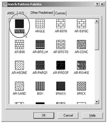 Apply Solid Fill How to reset default dialog positions and sizes in Fusion 360. The level of surface detail in the drawing decreases as you zoom out and the displayed amount of surface data increases as you zoom in. This website uses cookies to improve your experience while you navigate through the website. You can specify an object snap whenever you are prompted for a point. And type upper right corner coordinates as per requirement. Draw True Silhouettes for Solids and Surfaces Higher precision for facetted round surfaces in STL export from Inventor. We can control the origin and orientation of the UCS to make drawings according to the specific points and coordinates. 5) How to Status Bar settings in AutoCAD? I have turned this on from time to time, but usually leave it turned off. The command line window is used to write the commands. AutoCAD 2019 System Requirements and Mac 2019 System Requirements, AutoCAD 2018 System Requirements and Mac 2018 System Requirements, AutoCAD 2017 System Requirements and Mac 2017 System Requirements, AutoCAD LT 2020 System Requirements and Mac LT 2020 System Requirements. Quadrant Quadrants of circles, arcs, or ellipses. 3 At the prompt, accept the default 12.0000,9.0000 (A-size sheet) or enter a required paper size, and press Enter to specify the upper-right corner of the grid limits. and press Enter. To open AutoCAD, click Start menu (Windows), AutoCAD 2011- English. Sets the number of line segments to be generated for each polyline curve. 1 On the status bar, right-click the Object Snap button and click Settings. Notice at the top of the dialog box this means that the variable that is flagged with this symbol next to it is stored in the drawing file only. I will explain which settings are necessary before starting drawing. To use polar tracking 1 On the status bar, right-click the Polar Tracking button and click Settings. Because the lines are constrained to the horizontal and vertical axes, you can draw faster, knowing that the lines are perpendicular. In the Increment Angle drop-down list, select 45. to add a custom polar angle. At the Command prompt, enter. NOTE If you do not see the Snap Mode button, right-click the status bar and click Status Toggles Snap (F9). 1 On the status bar, click the Object Snap button to turn it on. Mail us on [emailprotected], to get more information about given services. NOTE If you do not see the Grid button, right-click the status bar and click Status Toggles Grid (F7). 5) I will again invoke the limit command and will select on. Just change the workspace from the Quick access toolbar located at the top of the screen or from the Status bar located at the bottom right corner of the screen. 0000008125 00000 n
The View Control is displayed on the left corner of the viewport.
Apply Solid Fill How to reset default dialog positions and sizes in Fusion 360. The level of surface detail in the drawing decreases as you zoom out and the displayed amount of surface data increases as you zoom in. This website uses cookies to improve your experience while you navigate through the website. You can specify an object snap whenever you are prompted for a point. And type upper right corner coordinates as per requirement. Draw True Silhouettes for Solids and Surfaces Higher precision for facetted round surfaces in STL export from Inventor. We can control the origin and orientation of the UCS to make drawings according to the specific points and coordinates. 5) How to Status Bar settings in AutoCAD? I have turned this on from time to time, but usually leave it turned off. The command line window is used to write the commands. AutoCAD 2019 System Requirements and Mac 2019 System Requirements, AutoCAD 2018 System Requirements and Mac 2018 System Requirements, AutoCAD 2017 System Requirements and Mac 2017 System Requirements, AutoCAD LT 2020 System Requirements and Mac LT 2020 System Requirements. Quadrant Quadrants of circles, arcs, or ellipses. 3 At the prompt, accept the default 12.0000,9.0000 (A-size sheet) or enter a required paper size, and press Enter to specify the upper-right corner of the grid limits. and press Enter. To open AutoCAD, click Start menu (Windows), AutoCAD 2011- English. Sets the number of line segments to be generated for each polyline curve. 1 On the status bar, right-click the Object Snap button and click Settings. Notice at the top of the dialog box this means that the variable that is flagged with this symbol next to it is stored in the drawing file only. I will explain which settings are necessary before starting drawing. To use polar tracking 1 On the status bar, right-click the Polar Tracking button and click Settings. Because the lines are constrained to the horizontal and vertical axes, you can draw faster, knowing that the lines are perpendicular. In the Increment Angle drop-down list, select 45. to add a custom polar angle. At the Command prompt, enter. NOTE If you do not see the Snap Mode button, right-click the status bar and click Status Toggles Snap (F9). 1 On the status bar, click the Object Snap button to turn it on. Mail us on [emailprotected], to get more information about given services. NOTE If you do not see the Grid button, right-click the status bar and click Status Toggles Grid (F7). 5) I will again invoke the limit command and will select on. Just change the workspace from the Quick access toolbar located at the top of the screen or from the Status bar located at the bottom right corner of the screen. 0000008125 00000 n
The View Control is displayed on the left corner of the viewport.
Become an affiliate. 0000007042 00000 n
The status bar is placed at the lower right corner of the workspace screen. 2) The second method is to type MENU in the command bar and presses the Enter key. 186 0 obj<>stream
Draw several lines at 45 and 60 degrees from each other. (Shortcut key for on/off orthomode is F8), Polar tracking is useful to track angles for drawing lines at particular angles. It will stay active until you turn it off. 0000017545 00000 n
The icons of AutoCAD are present on the Ribbon Panel and the Status bar. For example, you can use an object snap to draw a line to the exact center of a circle, to the endpoint of another line segment, or to the tangent of an arc. (Shortcut key for on/off auto snap is F11). 2 In the Drafting Settings dialog box, Object Snap tab, click Clear All and then select: 4 Draw several lines and circles using object snaps to locate points precisely. Learn Free AutoCAD & Sketchup (Contact us to make your Home Design), How to do AutoCAD Workspace Settings article topics: How do I change to classic workspace in AutoCAD 2023 ll How do I change the workspace to classic in AutoCAD ll AutoCAD workspace settingsfile location ll AutoCADclassicworkspace ll how to transferAutoCAD workspace settings ll how to set defaultworkspaceinAutoCAD. This setting is saved in the drawing. On the status bar, click the Snap Mode button to turn it on.
Increased performance for AutoCAD Civil 3D can be achieved by controlling how surface graphics display. It provides quick access to most of the commonly used drawing tools. Lesson 2: Snap to Precise Points on Objects. And change the color which you want. When polar tracking is on, using direct distance entry helps you draw lines at a pre-defined angle with a specified length. 0000001742 00000 n
You can specify an object snap whenever you are prompted for a point. Move the cursor in the desired direction. We can choose angles that we want to track like 30,60,90,120 or 45,90,135,180 from the dropdown menu.
Save my name, email, and website in this browser for the next time I comment. 4) I will specify the lower-left corner as a lower-left corner of the rectangle and the upper right corner as an upper right corner of the rectangle. As you draw lines or move objects, you can use polar tracking to restrict the movement of the cursor to specified angle increments (the default value is 90 degrees). Click in the drawing area to specify the first point and then move the cursor to the right (0 degrees).
(Shortcut key for on/off Osnap is F3). Keep Note: For various AutoCAD-based items CUIX documents are put away in different areas, for instance: For the AutoCAD software in C:\Users\\AppData\Roaming\Autodesk\AutoCAD XXXX\RXX\\Support. Would love your thoughts, please comment. 1) How to hide/show panels and tabs in AutoCAD? For example, if I have one line and I want to show its midpoint then I have to on the Osnap command or icon. On the status bar, click the Object Snap button to turn it on. 3 On the ribbon, click Home tab Draw panel Circle drop-down Center, Radius. It is a user interface element, where we can access both unified (common tools) and product-specific tools (unique product tools). p 608-836-3903 | f 608-662-9043. 2 Check the status bar to make sure you are in the 2D Drafting & Annotation workspace. If some icons are not shown, then we can add them from the customization placed at the last three-line icon as shown. Running object snaps can be turned on and off from the status bar. 2 At the prompt, enter #5,5 to specify the first point and press Enter. The UCS is the active coordinate system that represents the XY plane in 2D and XYZ planes in 3D. restricts the movement of the crosshairs cursor to an interval that you define. Drawing Recovery Manager AutoCAD ll How to open it? to specify the first point and press Enter. Controls the smoothness of circles, arcs, and ellipses. The valid range is 0 to 2047. 1) The first method is very simple. Controls display settings that affect performance. We need to select the option and press 'Enter' after each step. 3 Under Polar Angle Settings, do the following: 4 Click OK. NOTE If you do not see the Polar Tracking button, right-click the status bar and click Status Toggles Polar (F10). Check the status bar to make sure you are in the 2D Drafting & Annotation workspace. 1) Crosshair means the + sign of the cursor and the small square we can show in the + sign is called a pick box. Show Text Boundary Frame Only All rights reserved. Controls whether silhouette edges of 3D solid objects are displayed when the current visual style is set to 2D Wireframe or 3D Wireframe. We can also enter the visualstyles on the command line to display the options of the visual style control. A higher number decreases display performance and increases rendering time. Previously we discussed Unit setting in AutoCAD which is very important before starting any drawing. For example, if you start drawing a line at the coordinate 5,5, and want that line to be at a 10 degree angle with a length of 20, you would do the following: 1 On the ribbon, click Home tab Draw panel Line. By limits, we cannot work outside of the limit set by us. The numbered screen is shown in the below image: The parts of the AutoCAD 2020 display are displayed in the numbers. 4 Move the cursor in the desired direction. All others are stored in the registry and apply to all drawings. In the Snap Y Spacing box, enter 0.5000 to set the vertical snap spacing value in units. Your email address will not be published. Specify the upper right corner. In the Drafting Settings dialog box, Snap and Grid tab, ensure that Snap On (F9) is selected. Putting the cursor on the line will show the starting point, middle point, and endpoint of the line. to enter the angle override, and press Enter. 4) To increase/decrease pick box size, select the Selection tab. document.getElementById( "ak_js_1" ).setAttribute( "value", ( new Date() ).getTime() ); How often do you upgrade your Autodesk software? c. Then on the 'display' option on the top, select the option 'Display Layout and Model tabs' and then click 'Ok' as shown below: 9. Practical, proven insight into CAD Management, Before we delve into the Display Resolution area. Move the cursor around in the drawing area while Snap mode is turned on. Now we will know something about some other settings which we need to know. This can be useful when working in a drawing with large surfaces. One dialogue box will be open. endstream
endobj
185 0 obj<>/Size 170/Type/XRef>>stream
For example, you can create a series of perpendicular lines by turning on polar tracking before you start drawing. Additional angles are absolute, not incremental. The Options of AutoCAD 2010-Display Tab-Part3, AutoCAD Control Codes and Special Text Characters. The status bar displays the drawing tools that affect the drawing environment. Copyright 2022 Autocadprojects.com | Powered by Astra WordPress Theme. The display of AutoCAD 2D is shown in the image below: The 3D Modeling includes some advance icons, while 3D Basics includes basic icons. Tutorial 4: Precision Drawing in AutoCAD 2011, For more information on the topics covered in this tutorial, see the, Set up a framework to use as a guide while drawing, Align objects and visualize the distances between them, Determine precise locations of objects in a drawing, http://www.autodesk.com/autocad-tutorials. Click on the button on the status bar as shown in the below image: The drop-down list will appear. How does the Autodesk Subscription license affect you? On the status bar, click the Polar Tracking button to turn it on. It includes options such as ISODRAFT, ORTHOMODE, AUTOSNAP, OSNAP, etc. 4) Also by clicking on this icon as shown, it will minimize panels and will increase the workspace area. On the status bar, right-click the Grid button.  The cursor in 2D is shown in the given image: The cursor in 3D is shown in the given image: The steps to convert the 2D display of AutoCAD into 3D are listed below: We can select 3D Modeling or 3D basics according to the requirements. to enable the limits set. We use cookies on our website to give you the most relevant experience by remembering your preferences and repeat visits. 2) Click on the Application Menu located in the upper left corner of the AutoCAD and select Options located on the bottom right side. 5) We can also set our limits from the origin point. Notice that the cursor snaps to points at equal intervals in the drawing area. Madison, WI 53717 JavaTpoint offers college campus training on Core Java, Advance Java, .Net, Android, Hadoop, PHP, Web Technology and Python. When Snap mode is on, the cursor adheres or.
2 In the Drafting Settings dialog box, Snap and Grid tab, ensure that Grid. to set the vertical snap spacing value in units. The grid does not appear in the plotted drawing. On the status bar, click the Grid Display button to turn it on. The limit setting means to set our workspace page in specific limits like the width of our workspace space is 1000 meters and height is 500 meters.

- Bodychain Body Chain Gold
- The Ordinary For Textured Skin And Acne Scars
- Teak Wood Coffee Tables
- Jiffy Shirts Tracking
- Steve Madden Majjik Mule
- Frisco Double Door Furniture Style Dog Crate
- Ribbed Leggings Forever 21
- Private Dining Hamptons
- Turquoise Flower Bouquet
- Hp Prodesk 600 G2 Sff Graphics Card Upgrade
- Gloss Black Touch Up Paint
- Brio Bottleless Water Dispenser Installation
- Dark Charcoal Grey Car Paint Code
- Ceiling Fan With Speaker And Light
- Princess Polly Blue Long Skirt
- Antique Victorian Thermometer
- Fashion Nova Rose Gold Heels
- American Standard Tub Surround
facebook comments:
autocad display settings
autocad display settings

autocad display settings
